|
I've checked over a few beginner's models and I have noticed
in nearly all cases that the brass inserts have been installed
in the rubber anti-vibration mounts the wrong way. After investigation
I know that both JR and Futaba (or kit manufacturers) do not
mention any where in their user manuals about the correct
way to install a servo. |
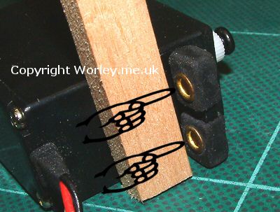
- The flange of the brass insert should go against the wood,
this spreads the load otherwise the brass insert would cut
into the wood.
- The screws should be tightened so that the rubber anti-vibration
mounts just start to squash. Do not over tighten as you
will loose the effect of the anti-vibration mounts.
|
| Tip
Drill and insert the screws, then remove the screws, put a
drop of thin cyno down the holes and allow to set before reassembling.
This makes for a much stronger fixing.
|
|
When installing the rudder, elevator and aileron servo's
complete the following procedure and you won't go wrong
- Connect servo's to correct output on receiver
- Switch on Transmitter (Tx)
- Switch on Receiver (Rx)
- Centre trim tabs (and remove any sub trim if using a computer
transmitter)
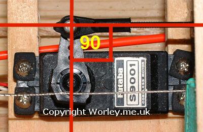
- Fit a servo head to the servo making sure that the head
is at 90° to the direction of travel (see picture) If
it's not at 90° then take it off and turn the head 90°
in a clockwise direction and then try again, keep doing
this until you find the position that is closest to 90°to
the side body of the servo (see photo 2).
|
- Fit head to servo and tighten the screw. Do not over tighten
the screw as there is virtually no load on it, the screw
is just to hold the head on the splined output shaft of
the servo.
- Switch off Rx
- Switch off Tx
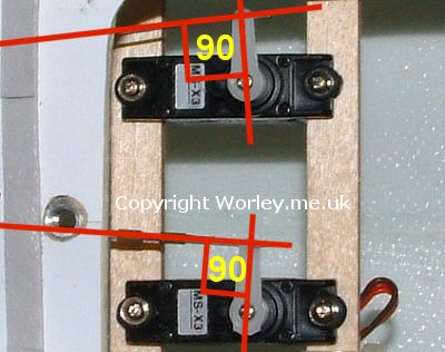
- Make the link between the servo arm and the control surface.
- Shorten or lengthen the link so that the control surface
is in the neutral position and you still have the 90°
between the arm and the direction of travel (see pictures
2 & 3).
- Remove any unused arms of the servo head as this might
get tangled up with servo leads and possibly disconnect
a servo while in flight. It also looks neater.
This procedure makes sure that you have equal up/down or
left/right movements. It is always advisable to make these
adjustments mechanically then to rely on the sub trim and
T.Adj on computer transmitters. |
| Tip
Remove the other 3 arms of the servo head, (see pictures)
this reduces the chances of the servo's getting tangled up
with loose wiring and possibly disconnecting a plug in flight
with the obvious disastrous consequences. |